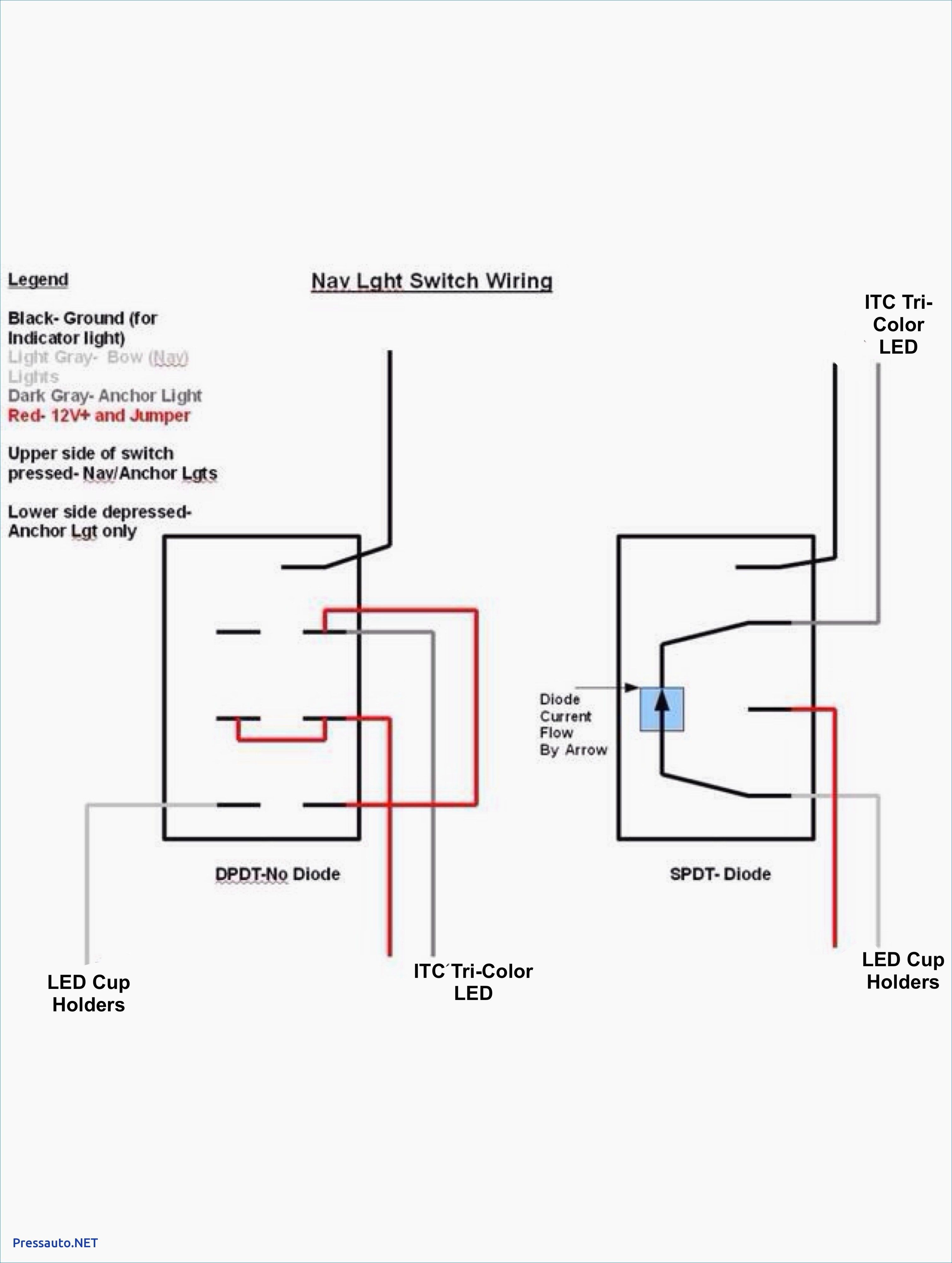
Unbelievable Spdt Rocker Switch Wiring

You would most often use the vjd2 instead of the vjd1 when this switch will be triggering two loads but not the backlights in a bank of backlit rocker switches.
Spdt rocker switch wiring. Wire the spdt switches. Okay so in this video we re going to insert the aa batteries into our battery holder. Below is the schematic diagram of the wiring for connecting a spdt toggle switch.
Notice on the wiring diagram that of the 10 prongs spade connectors called termianls on the back four 4 make the rocker switch lights function while the remaining six are used for the electromechanical switching contacts. There is also an illuminated push button wiring diagram here and a complete kit wiring diagram here. Create the motor mounts.
Most rocker switches are of the single position. The diagram below represents the schematic diagram for a spst rocker switch. Connect the leds to an on off switch.
Pin 2 is where the accessory that the switch is going to turn on is connected. So a spdt switch can power either one of 2 circuits. And terminal 3 can connect to any load to power any device.
Pin 3 is where the switch is either connected to ground or left open. Spout in a maze. An illuminated rocker switch is like a spst toggle switch with an extra terminal which allows the light to work.
Secure and wire the motors. A spdt toggle switch has 3 terminals. Der klassische wechselschalter ist einpolig und nennt sich single pole double throw spdt.


