Perfect 3 Phase Potential Transformer Connection Diagram
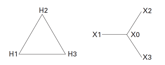
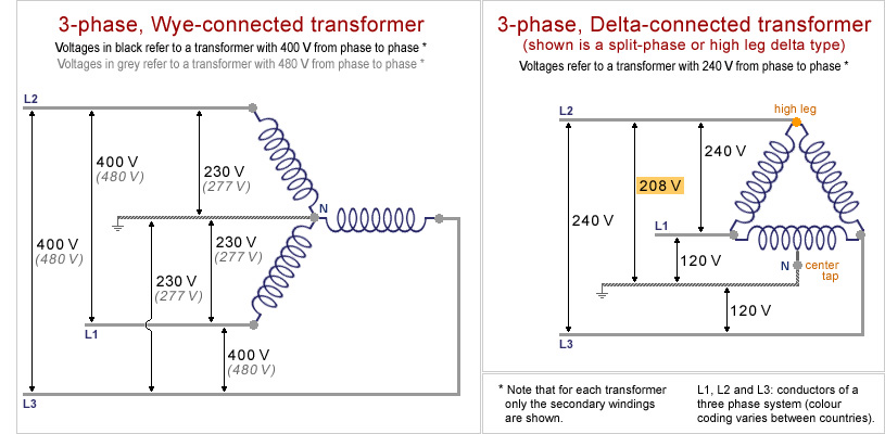
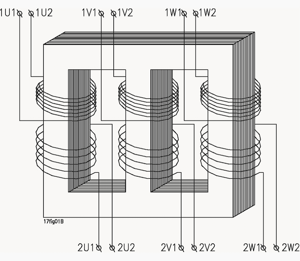
A three phase transformer is built for a specific connection and voltage transformation and the unit will have a nameplate with the internal connections shown.
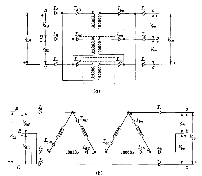
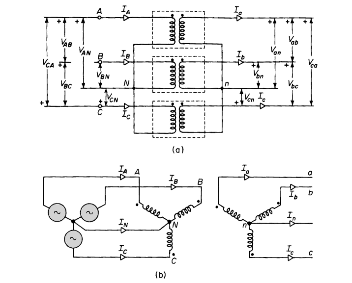
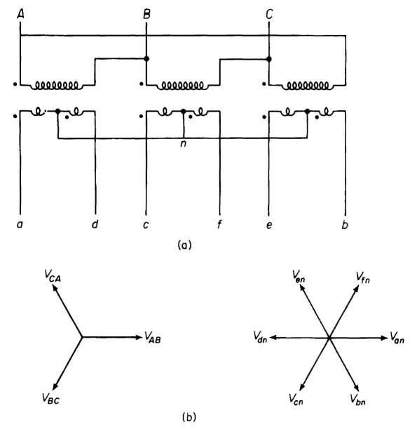
3 phase potential transformer connection diagram. The dashed lines indicate the transformer outlines. Only one phase is shown b and c phases are duplicated with secondaries connected as in a. Basic connection of voltage potential transformer phase phase.
Connecting to 2 transformers so called v connection. Requires 1 isolated mv terminal for each transformer. Star wye delta mesh and interconnected star zig zag.
Requires 2 isolated. It provides recommended wiring diagrams and information on the measurements. Note that there is no neutral line in the wiring diagram.
In the case of three phase transformerwindings three forms of connection are possible. In this the polarity side of a phase is connected to the non polarity side of c phase. For the three phase transformer the.
You may also read. Metering connection arrangements for voltage potential transformer star connection of 3 transformers. Taps may be provided to obtain either 69 3 v or.
This transformer step down the voltage to a safe limit value which can be easily measured by the ordinary low voltage instrument like a voltmeter wattmeter and watt hour meters etc. Y y y y and. The phasor diagram of the y connection of the three phase transformer is shown in the figure below.
